Free Book Power Transmission And Distribution Seconde Edition By Anthony J. Free Book Power Transmission And Distribution Seconde Edition By Anthony J. Free Book Power Transmission And Distribution Seconde Edition By Anthony J. Electricity generation and transmission concept. The purpose of the electric transmission system is the interconnection of the electric energy producing power plants or generating stations with the loads. A three-phase AC system is used for most transmission lines. The operating frequency is 60 Hz in the U.S. And 50 Hz in Europe, Australia, and part of Asia. Introduction-.To become familiar with the function of different components used in Transmission and Distribution levels of power systems and modeling of these components.To develop expression for computation of fundamental parameters of lines.To categorize the lines into different classes and develop equivalent circuits for these classes.
Electricity generation and transmission concept
The purpose of the electric transmission system is the interconnection of the electric energy producing power plants or generating stations with the loads. A three-phase AC system is used for most transmission lines.
The operating frequency is 60 Hz in the U.S. and 50 Hz in Europe, Australia, and part of Asia.
The three-phase system has three phase conductors. The system voltage is defined as the RMS voltage between the conductors, also called line-to-line voltage. The voltage between the phase conductor and ground, called line-to-ground voltage, is equal to the line-to-line voltage divided by the square root of three.
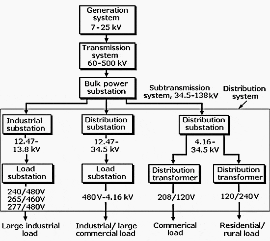
The generating station produces the electric energy. The generator voltage is usually around 15 to 25 kV. This relatively low voltage is not appropriate for the transmission of energy over long distances. At the generating station a transformer is used to increase the voltage and reduce the current.

In Figure 1 the voltage is increased to 500 kV and an extra-high voltage (EHV) line transmits the generator-produced energy to a distant substation.
The voltage is reduced at the 500 kV/220 kV EHV substation to the high voltage level and high voltage lines transmit the energy to high voltage substations located within cities.
At the high voltage substation the voltage is reduced to 69 kV. Sub-transmission lines connect the high voltage substation to many local distribution stations located within cities. Sub-transmission lines are frequently located along major streets.
Power System Transmission And Distribution Pdf
Electricity distribution concept
The voltage is reduced to 12 kV at the distribution substation. Several distribution lines emanate from each distribution substation as overhead or underground lines. Distribution lines distribute the energy along streets and alleys.
The distribution transformer reduces the voltage to 230/115 V, which supplies houses, shopping centers, and other local loads. The large industrial plants and factories are supplied directly by a subtransmission line or a dedicated distribution line as shown in Figure 1 above.
All documents, EE software and EE books are free to download.
Table of Contents
Electrical Power Transmission And Distribution Pdf
- 1: Transmission and Distribution: AN Introduction
- 1.3 - CONVENTIONAL SOURCES OF ELECTRICAL ENERGY
- 1.4 - LOAD FORECASTING
- 1.5 - LOAD MODELLING
- 1.6 - STAR-CONNECTED LOADS
- 1.7 - DEREGULATION
- 2: Transmission-Line Parameters
- 2.6 - CURRENT DISTORTION EFFECT
- 2.7 - INDUCTANCE
- 2.11 - INDUCTANCE OF THREE-PHASE LINES
- 2.12 - INDUCTANCE OF THREE-PHASE DOUBLE CIRCUIT LINE
- 2.17 - CAPACITANCE OF THREE-PHASE LINES
- 2.18 - CAPACITANCE OF A THREE-PHASE DOUBLE-CIRCUIT LINE
- 2.19 - EFFECT OF EARTH ON TRANSMISSION LINE CAPACITANCE
- 3: Performance of Short and Medium Transmission Lines
- 3.4 - SHORT TRANSMISSION LINE
- 3.7 - MEDIUM TRANSMISSION LINE
- 4: Performance of Long Transmission Lines
- 4.3 - INTERPRETATION OF THE LONG LINE EQUATIONS
- 4.6 - EQUIVALENT CIRCUIT REPRESENTATION OF LONG LINES
- 4.12 - CHARGING CURRENT IN LINES
- 4.15 - CIRCLE DIAGRAM
- 5: Transmission Line Transients
- 5.9 - REFLECTION AND REFRACTION COEFFICIENT (LINE TERMINATED THROUGH A RESISTANCE)
- 5.12 - REACTANCE TERMINATION
- 6: Corona
- 6.7 - FACTORS AFFECTING CORONA LOSS
- 6.13 - INTERFERENCE WITH COMMUNICATION LINES
- 7: Mechanical Design of Transmission Line
- 7.3 - LINE SUPPORTS
- 7.4 - SAG
- 8: Overhead Line Insulators
- 8.3 - TYPES OF INSULATORS
- 8.4 - POTENTIAL DISTRIBUTION OVER A STRING OF SUSPENSION INSULATORS
- 8.6 - METHODS OF IMPROVING STRING EFFICIENCY
- 8.8 - TESTING OF INSULATORS
- 9: Underground Cables
- 9.3 - TYPES OF CABLES
- 9.5 - PROPERTIES OF INSULATING MATERIALS FOR CABLES
- 9.10 - GRADING OF CABLES
- 9.12 - CAPACITANCE OF A THREE-CORE CABLE
- 9.13 - HEATING OF CABLES
- 9.14 - THERMAL CHARACTERISTICS
- 9.15 - TESTING OF CABLES
- 9.16 - LAYING OF CABLES
- 10: Power Factor Improvement
- 10.2 - POWER FACTOR
- 10.4 - METHODS OF IMPROVING POWER FACTOR
- 11: Voltage Control
- 11.5 - METHODS OF VOLTAGE CONTROL
- 12: Electric Power Supply Systems
- 12.2 - COMPARISON OF CONDUCTOR EFFICIENCIES FOR VARIOUS SYSTEMS
- 12.7 - ECONOMIC SIZE OF CONDUCTOR (KELVIN'S LAW)
- 13: Substations
- 13.3 - CLASSIFICATION OF SUBSTATION
- 13.6 - TYPES OF BUS BAR ARRANGEMENTS
- 13.8 - OPTIMAL SUBSTATION LOCATION
- 13.12 - METHODS OF NEUTRAL GROUNDING
- 14: Distribution Systems
- 14.2 - PRIMARY AND SECONDARY DISTRIBUTION
- 14.4 - DISTRIBUTION SYSTEM LOSSES
- 14.5 - CLASSIFICATION OF DISTRIBUTION SYSTEM
- 14.9 - DC DISTRIBUTION
- 14.10 - RING DISTRIBUTION
- 14.12 - AC DISTRIBUTION
- 15: Ehv and Hvdc Transmission Lines
- 15.6 - COMPARISON BETWEEN AC AND DC TRANSMISSION SYSTEMS
- 15.8 - HVDC TRANSMISSION SYSTEM
- 16: Flexible AC Transmission Systems
- 16.3 - FACTS CONTROLLERS
- 16.4 - CONTROL OF POWER SYSTEMS
- 16.5 - BASIC RELATIONSHIP FOR POWER-FLOW CONTROL
- 16.7 - VOLTAGE STABILITY